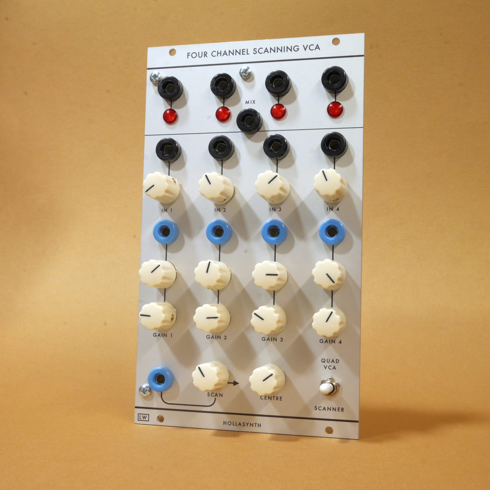
Hollasynth Four Channel Scanning VCA

What is it?
The Hollasynth four-channel scanning VCA is a version of Jurgen Haible’s Interpolating Scanner idea, in 4U Serge-compatible format, complete with a beautiful front panel by Loudest Warning
It is a four-channel voltage controlled crossfader. As the scan CV is swept from 0V to 5V, the mix output fades from channel 1, through a mix of channel 1 and 2, to channel 2, then fades to channel 3 and finally channel 4. In addition to the main mix output, there is an individual output for each channel. Front panel knobs provide an offset and attenuversion on the scan CV.
The gain of each channel is also individually controllable, so the module can be used as a four channel VCA as well. A switch allows the scanning control to be disabled so that only the VCA CV affects channel gain. Finally there are attenuator for the gain CV and initial gain knobs on the front panel.
What can I do with it?
Probably more than I can! But try some of these:
- Crossfade between the wave shapes of a VCO for voltage-controlled morphing, e.g. from sine to saw to triangle to square and back. Like this.
- Crossfade between up to four audio sources under voltage control. Like this.
- Voltage controlled CV mixing. The inputs and outputs are DC coupled so you can use the module to mix and morph between CV sources
- Voltage controlled signal switching. By appying stepped CV to the scan input, e.g. from a sequencer, you can switch between signals rather than fading… if you get the CV set up just right! Like this
- Audio Waveshaping. Patch fixed voltages or LFOs or whatever you like into the signal inputs. Send an audio rate 0-5V sawtooth into the scan CV. Use the mix output as am audio signal. Like this. Or like this. (Thanks, Loudest Warning!)
How does it work?
The scanner contains four linear VCAs, one per channel, based on the LM13700 IC. Each VCA is controlled by the sum of two CVs: the direct VCA CV and the scanning CV. The scan CV is provided by a version Don Tillman’s beautiful scanner implementation, used with his kind permission. (But please don’t bug him if you have issues with the module!)
Build notes
- Bill of materials
- Interactive BOM to help place the parts (experimental!)
- Schematic – main PCB
- Schematic – panel PCB
You don’t really need to match the transistors. In principle the thing would work more accurately if the transistors in the core were matched for Vbe, but I have never bothered and all my builds seem to work fine.
Build process suggestions
Carefully snap the two PCBs apart before you begin.
Place and solder all the 0805 SMD capacitors on the rear of the main PCB first. My build order after that is: diodes, resistors, ferrite beads, IC sockets, ceramic capacitors, transistors, electrolytic capacitors, power connector.
Then I build the panel PCB. First solder R101. I have forgotten this component in every build so far. Don’t be like me.
Next I snap in the pots, then mount the PCB to the panel and secure gently with the potentiometer nuts to ensure good alignment before soldering. Then I unmount the panel again and re-read the note on the PCB that suggests hand-wiring would be easier, which I agree with, because I wrote it and because it would. Kids these days.
Next I solder the header pins. I seat the male pins in the female sockets and assemble the PCB sandwich so that I can be sure the headers all align correctly, then solder while everything is in place.
The final step is to finish up the panel. I mount all the jacks to the panel, insert LED lenses into the panel holes, and place the LEDs and switch in place on the control PCB without soldering. With the switches I use, the right spacing is achieved with just the tooth-nut between the switch and the panel. I mount the control PCB to the panel again, secure the pots with their nuts, slide the LEDs through so that they are seated in their lenses, and solder.
Finally I solder short lengths of wire to the banana jacks and connect to the pads on the control PCB. Reassemble the PCB sandwich and you’re done.
Setup
There are two adjustable settings: the CV offset trimming for the VCAs (TR1 - TR4) and the scanner sensitivity (TR5).
To trim the VCA offsets, first unplug any patch cables. Put the switch in VCA position. Turn the input attenuators to zero and the initial gain knobs full clockwise: each VCA will be fully on but receiving 0 signal. Measure the output on channel 1 with a voltmeter and adjust TR1 until the output is as close to 0V as possible. Do the same with channel 2 and TR2, and then the remaining channels.
Alternatively, if you do not have a multimeter, you can trim by ear. Set the switch to VCA position. Turn the input attenuators and initial gain knobs to zero. Send a 50Hz square wave into the CV input of the channel you are trimming, and monitor the audio output. Adjust the trimmer (TR1 for channel 1, etc) until the output is as quiet as possible.
TR5 adjusts the rate at which the scanner fades from one channel to another. This should simply be adjusted to taste.